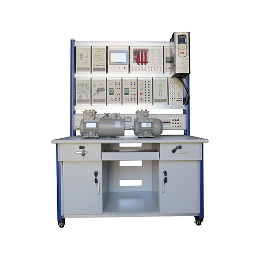
AAC-1 Modular Educational Systems For Drives Of AC Motors Teaching Equipment Electrical Workbench
System mod. AAC-1 has been designed and manufactured with industrial components according to educational standards. It is the suitable tool for the theoretical-practical study of AC motor drive. TECHNICAL CHARACTERISTICS: Trainer mod. AAC-1 consists of three units for the exhaustivestudy of the industrial drive of an AC motor. These units are: A1A AC DRIVE - Microprocessor module A2A AC MOTOR CONTROL - Power circuit MDAQ - Data acquisition module The development of the exercises of the training programconsists in fixing the units in the support mod. TSI-1, placingover the due overlay for the exercise under test and arrangingthe proper connections. Each unit includes a panel of insulating material with Ø = 4 mmsafety terminals, for connections. Connecting module MDAQ will supply the (opto-isolated)signals of voltages and currents of unit A2A. A1A AC DRIVE –Microprocessor module Module A1A is connected with module A2A via a 25-poleconnector and enables its operation by generating thenecessary signals for control of power circuits. It includes a 4-line alphanumeric display to show various data,such as the codes of the module and of the connected overlay,the set point value, the selected control mode (open or closedloop, with tachogenerator or armature voltage) etc... ThisModule includes a PID controller for the speed of the AC motorcoupled to a tachogenerator (motor & tachogenerator are notincluded), connected with unit A2A. It is possible to set the P, I and D values and the acceleration& deceleration ramps. The on-board pushbuttons enable thenavigation through the menu, and the potentiometers allow tomodify the selected parameters. Furthermore two other analoginputs of 0 to 10 V are available for the connection with anysource of external signals. A2A AC MOTOR CONTROL –Power circuit Unit A2A includes the power circuits for the AC motor. It consists of a VSI-type three-phase inverter whose controlsignals come from unit A1A. This three-phase inverter includes6 IFBT transistors. The maximum power of motors that canbe connected is of approximately 1000 W. A “Chopper”-typebraking circuit is available and two Ø = 4 mm safety terminalsenasble to control motor overtemperature. The DC powersupply for the inverter comes from a Graetz bridge withcapacitor fi lter. Three Ø = 4 mm safety terminals available onthe panel enable to connect this unit with the three-phasemotor. Other two specifi c Ø = 4 mm safety terminals allowthe connection with a tachogenerator for closed loop control.Connecting module MDAQ with 15-poleconnectors will supplythe (opto-isolated) signals of voltages and currents available inthe circuit. MDAQ - Data acquisition module Module MDAQ supplies the (opto-isolated) signals of the unitwhich it is connected with, on 30 safety terminals (Ø = 2 mm). The opto-isolated signals ensure electrical safe conditionsfor students when carrying out measurements: for instance,it is not necessary to use differential probes when usingoscilloscope. Supply with THEORETICAL – EXPERIMENTAL HANDBOOK